1. SAFETY & COMPLIANCE
This equipment and its components have been tested and found to comply with the limits for a Class B digital device, pursuant to Part 15 of the FCC rules. These limits are designed to provide reasonable protection against harmful interference in a residential installation. Modifications not expressly approved by the manufacturer or registrant of this equipment can cause injury or damage.
There are some safety considerations to avoid potential hazards that could harm you or others or cause product or property damage:
HOT SURFACE: Do not touch any part of the LILY Pellet Extruder during operation, temperatures above 200ºC. Always allow the extruder to cool down before touching it directly.
MOVING PARTS: The LILY Kit includes moving parts that can cause injury. Do not insert fingers or hands while in operation.
DONT LEAVE UNATTENDED: Avoid leaving The LILY Kit unattended during operation. If you must leave the LILY Kit unattended during a print, exercise caution and follow these guidelines:
- Verify that The LILY Kit has started the print and is operating normally.
- Ensure that enough granule feedstock is stored in the Auto Pellet Dispenser and that the hose is free of tangles so that feedstock is being delivered properly.
- Monitor your print periodically.
UNTESTED MATERIALS: Use caution when printing with materials that have not been tested by recycl3dprint for use with The LILY Kit.
DISCONNECT WHEN NOT IN USE: In case of emergency disconnect the power supply from the wall socket. The socket-outlet must be located near the equipment and must be easily accessible.
PLASTIC FUMES: The LILY Kit melts plastic during extrusion and plastic odors are emitted during this process. Make sure to set up the LILY Kit in a well-ventilated area.
COOLDOWN TIME: Never disconnect the LILY Kit during or immediately after printing. Always allow the extruder to cool down completely before turning off your 3D printer or disconnecting in order to avoid clogging.
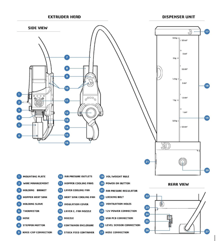
2. Getting Familiar With The LILY Kit
3. Installing The LILY Pellet Extruder
In order to install the LILY Pellet Extruder into your filament 3D printer, we offer 2 options. The first is a direct bolt-on via the pre-installed mounting plate and the holding bracket. That works for the most common carriage designs. The Second option is fixing the LILY pellet Extruder onto the 3D primer carriage via a coupling plate. Those two options are explained in more detail in the next two subsections.
3.1 Direct bolt-on via pre-installed mounting plates
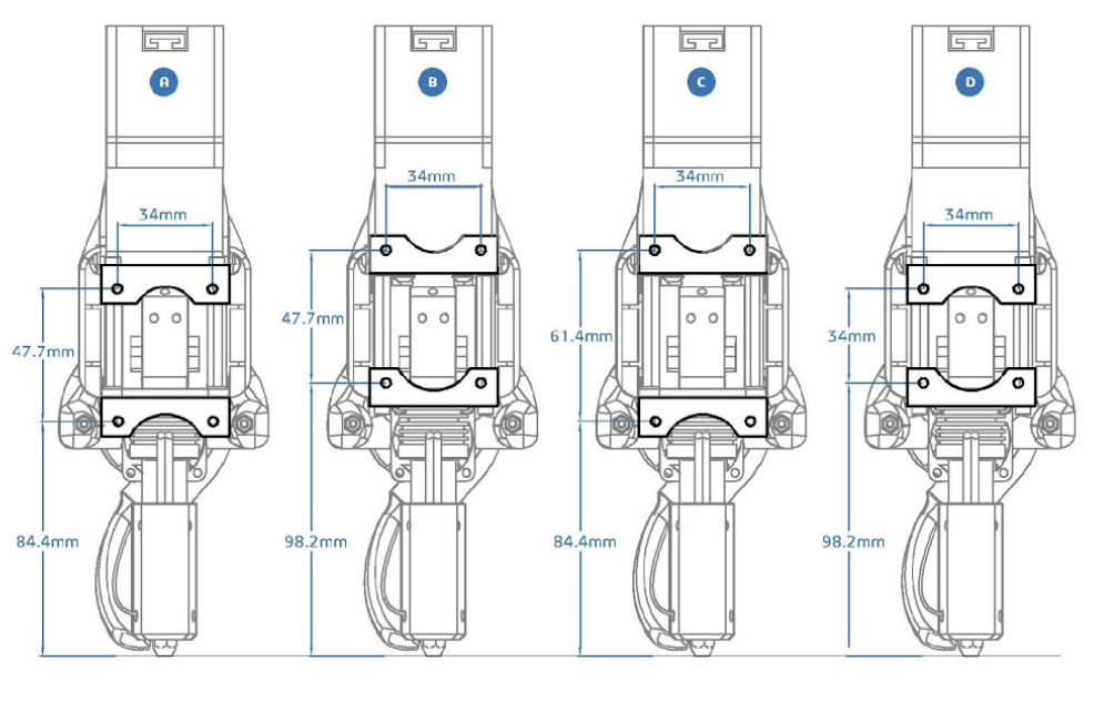
Depending on the orientation of the mounting plate and holding bracket the vertical distance between the screw holes will change (see diagram below). The different vertical distances that can be reached with the 4 configurations will allow you to match the hole layout of the most common 3d printer carriages. In case none of the 4 configurations helps to match the hole layout for the carriage of you printer, please read
OPTION A (facing downwards): 34mm width x 47.7mm high/84.4mm clearance.
OPTION B (facing upwards): 34mm width x 47.7mm high / 98.2mm clearance.
OPTION C (facing outwards): 34mm width x 61.4mm high / 84.4mm clearance.
OPTION D (facing inwards): 34mm width x 34mm high / 98.2mm clearance.
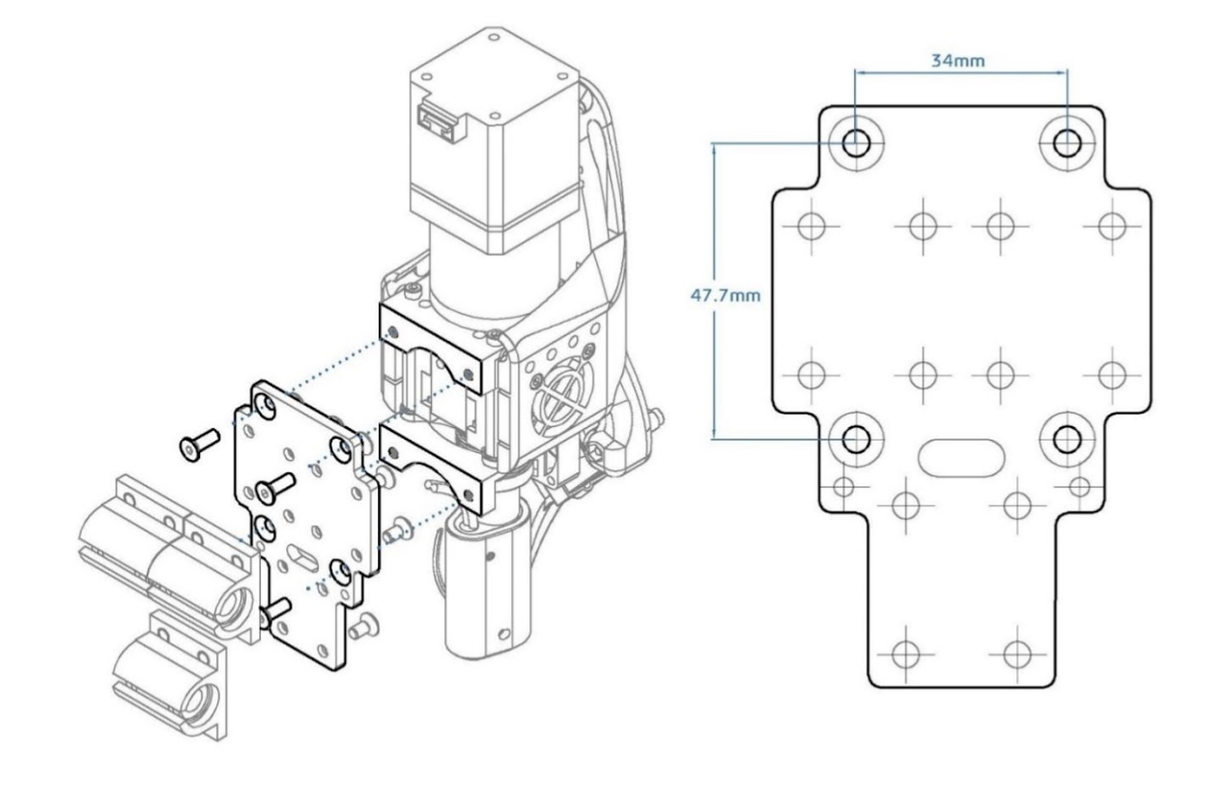
3.2 Indirect bolt-on via coupling plate
What to do in case none of the 4 configurations helps to match the hole layout for the carriage of your printer? You can either drill additional holes into the carriage, this is the most straightforward way. Alternatively, you can create a coupling plate, that allows you to use the non-matching hole layouts of the carriage and the LILY Pellet Extruder (see example coupling plate below for a Prusa style printer)
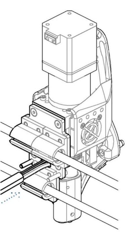
3.3 Cable Management
4. Connecting the LILY Pellet Extruder to you 3D Printer
How to identify cables?: All cables are clearly marked with labels that are attached to each cable.
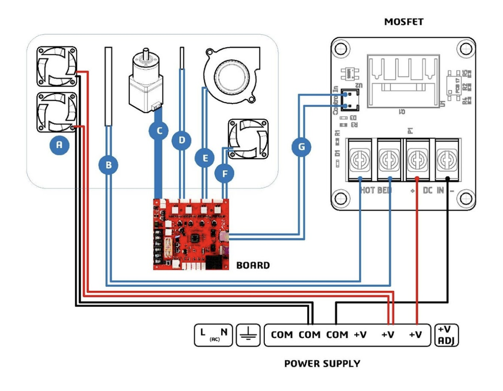
How to connect the cables: Please follow the schematic below, which will explain to you how to do the following wiring.
Extruder → 3D Printer Board
Extruder → Mosfet
Mosfet → 3D Printer Board
- From the bundle connect the cables of the extruder motor (C), thermistor (D), the layer fan (E) and heat sink fan (F) to the board as normal.
- Connect the control wires (G) of the MOSFET to the board where the heating cartridge should be.
- Connect the DC IN +/- terminals to your printer’s power supply and insert the heating cartridge wires (B) into the terminals labeled “HOT BED”. Recommended the use of crimped connections.
- Connect the hopper cooling fans (A) directly to the power supply.
5. Firmware Configuration
1.- Set the steps/mm of the extruder between 900-600steps/mm. Initially recommended 800steps/mm.
2.- Set the thermistor NTC3950 (280ºC) or HT-NTC100K (350ºC);
Usually #5 and #13 respectively on Marlin:
#define TEMP_SENSOR_0 5
3.- Set the extruder PID by running Autotune PID for accurate values or set initially the default LILY v 5.1 PID:
- #define DEFAULT_Kp 38.73
- #define DEFAULT_Ki 2.72
- #define DEFAULT_Kd 137.84
4.- Set the new margins on the machine according to the new position of the nozzle
5.- Tweak if necessary the velocities and accelerations according to your 3D printer and new masses and ultimately the jerk values (override with M205 X Y Z E).
7.- Increase if necessary the manual feed rate of the extruder for a faster purge:
#define MANUAL_FEEDRATE {50*60, 50*60, 4*60, 5*60}
6. Commands via Interface
1.- M106 F255 // Switch on layer fan (if needed)
2.- M92 E(steps/mm) // Set steps per millimeter.
3.- M205 E 0.03 // Set a low Jerk for the extruder.
4.- M303 E0 S220 C3 // Run PID autotune for the extruder at 220ºC three times
5.- M301 P38.73 I2.72 D137.84// Set PID
7. Slicer Software Settings
1.- When using large nozzles vertical lift can help to avoid losing steps.
2.- Purge the nozzle may help to get clean extrusion when starting a print.
G28; home all axes
G92 E0; zero the extruder length
G1 F200 E25 ; extrude 25mm
G92 E0; zero the extruder again
G1 X20 Y30 Z-0.08; guillotine